Pages

Saturday, December 31, 2011

Proper Electrical Connections

IMG_2310
   These are something that has no place on a boat - wire nuts.
On Board with Mark Corke shows us the correct way for wire terminals. He says....
I recently surveyed a power cruiser which had lots of alterations to the electrical system, not only were many of the connections made with wire nuts the cable was solid core rather than multi strand tinned boat cable, both of which are a big no-no on a boat. Wire nuts are not moisture resistant and cable with a solid core is susceptible to vibration and fatigue eventually leading to failure.
For the complete step by step guide to making proper electrical connections continue reading ..

Wiring on a boat leads a hard life; corrosion, vibration and chafe all conspire against your boats electrical system to bring it to a premature end. Bad connections are to blame for many problems and knowing how to make proper crimped terminals will go a long way to avoiding problems. Simply twisting wire together, using wire nuts or wrapping it round a terminal screw simply will not do. Proper crimped terminals are neat, allow the free movement of electricity and prevent short circuits. It is a good idea to have some practice runs on some spare bits of cable so that you are able to make perfect joints every time. Tug on the connector to test the integrity of the completed joint; if there is any movement or the terminal comes off you need to cut back the cable and start afresh. Terminals and cables come in a variety of sizes measured by what is called gauge; the smaller the number the larger the cross sectional area of the cable conductor and therefore it’s ability to carry higher electrical loads. Always make sure that you use the correct size cable for the maximum amount of the current that the cable will have to handle. Finally only ever use tinned marine cable on a boat. Untinned cable is cheaper but is very susceptible to corrosion.


Tools and materials needed
Cable
Crimping terminals
Heat shrink the same color as the cable
Crimping pliers
Wire strippers
Heat gun

Tip
Making proper terminal connections is very straight forward and easy but it pays to have a trial run with some scrap cable to get the feel for how things should go.


Wire1
1. Cut back any suspect and ragged ends using a pair of side cutters or the cutters built into the crimping tool. This is especially important if the wire is at all corroded. You can skip this step if using fresh new cable from a drum.

Wire2
2. Strip off the insulation from the wire being careful to cut only through the sheathing and not into the actual wire. Remove only sufficient insulation to allow the wire to be entered fully into the terminal with no bare wire visible.
Wire3
3. Grasp the wire in one hand and with the other twist the strands together between thumb and forefinger.  This binds the strands tightly together which makes pushing the cable end into the terminal easier.

Wire4
4. Cut a length of heat shrink about an inch long the same color as the cable insulation and slip this onto the wire.
Wire5
5. Slide on a terminal connector to the end of the cable and after ensuring that it is pushed fully home use the crimping pliers and squeeze it onto the wire. Note that the crimping jaws are color-coded. The colored dot on the plier jaws must correspond with the color of the terminal.
Wire6
6. Slide the heat shrink back up the cable so that it covers the crimp completely then use a hot air gun or a match shrink it into place. Do not apply too much heat; warm it just sufficiently to shrink it to the cable.
Wire7
7. The completed job. A perfect electrical connection, which should give years of trouble free service.

Friday, December 30, 2011

Propellor Clearance

IMG_0032
It is essential to have the correct amount of tip clearance between the end of the propeller blades and the hull. The recognised minimum clearance  should be between one sixth and one fifth of the total prop diameter. Therefore with a 16 inch blade like the one in the picture we should be looking for about a 2 and half inch clearance at least What there is in fact is so little room that it was impossible to get even the end of my pen between the underside of the hull and the blade tip. The way that a prop works is fairly complex and it creates lift and thus drives the boat forward. When the tip clearance is compromised two things happen; the first is that the water flow is interrupted and the blade will not be anything like as efficient and secondly the water is 'trapped' between the rotating prop and the hull. With each revolution this slap will be felt inside the boat as added vibration. The only way around this problem in this particular case would be to either have a slightly longer shaft to move the prop away from the boat a little but even that I doubt would not be enough or secondly would be to go for a different prop of perhaps a smaller diameter but with a slightly increased pitch.
As a footnote the generally accepted practice is that the shaft should project no more than one and a half times it's diameter past the end of the cutless bearing.

Thursday, December 29, 2011

Fuel Filter Indicator

Fuel filter service ind
 One of the issues with any fuel filtration system is that you never know exactly when the filters need replacing or are restricted in some way. One method is to install a drag gauge into the system which will show just how much 'suck' there is in the vacuum side of the pump, the greater the drag, the higher the reading and thus more the fuel fuel flow and filters are clogged. It is a great system but comes at a price and complications which many recreational boat owners can do without. A simpler solution is the fuel flow service indicator from Racor. Essentially this simple but effective bit of kit is teed into the fuel line on the vacuum side of the line between the filter and the pump. As the vacuum increases a yellow disc is sucked down in the clear bowl. While the disc is in the green sector all is well but as the pump has to suck harder as the fuel filter becomes blocked it enters the red sector indicating the need for a filter change. I should add that the disc stays at the highest setting achieved even after the engine is shut down so it is possible to monitor the performance of the filters even when the engine is off and cold. Once filters have been changed the operator merely has to press the button on the top of the unit and the disc resets. The cost is a very sensible $60 and can be had from West Marine and other such suppliers.

Wednesday, December 28, 2011

New Table Hand Saw

Here's a very nice tool I would love to add to my collection.

Tuesday, December 27, 2011

PYI Mini Floor Anchors

Mark Corke has this to say about the PYI Mini Floor Anchors. An excellent web site from Mark; and a useful  product. He says.......


  I wrote some time back about PYI anchors and indeed installed some on my own boat to hold the cabin sole in position so was excited to learn that my good friends at PYI have come out with a new product called the mini anchor which is aimed primarily at the OEM market. The basic principles are the same as the original product but instead of having the bayonet style latch the smaller anchors screw together and need to be undone with a screw driver rather then using a quarter dollar coin as it is possible to do with the larger versions.

As I was unfamiliar with the new anchors I thought it best to have a trial run so that next time when I want to use them I have the confidence to install them without fear of messing things up. You don't need a lot of tools but you do need to be careful in your marking out or the parts won't line up and the results could be disappointing this could be especially frustrating if you are using them on expensive teak and holly sole plywood.
L1020379
 
The anchor consists of three parts The screw part that is held in place in the sole or other panel and actually screws into the bottom half, that,s the larger of the two bits that you can see in the picture and finally the flat locking nut that you only need if you attach the female part to something like an aluminum floor member. Lastly the other bit is the tool that you need to screw the female part into the boat. As this was a trial run I was able to do this at the work bench and therefore use a pillar drill. A hand held electric or rechargeable drill work just as well but be sure to keep in perpendicular to the surface.
 L1020382
The next step is to mark out where you want the anchors to be placed. This is definitely one of those time that you should check twice and drill once. Aim not only for a neat appearance but try to ensure that you will not be placing the anchors too close to an edge or worse still be drilling into a cable or pipe hidden from view. This was just a trial for me so I did not have any of those worries, but be neat. Mark the drilling centers with a crisp pencil mark, if installing into a pre finished cabin sole then I would have stuck a piece of masking tape down and made a mark on that.
 L1020384
The male part of the anchor is retained within a sunk cup and this needs to be a good fit as the anchor is simply a push fit. A 9/16th bit is exactly the right size I found. A Forster bit would have been better but I did not have one of the of the correct size so I want ahead and used a standard twist bit which I made sure was sharp. I used some tape to mark the depth that I needed which is the depth of the cut and no more, refer tot he drawing and you will see how this insets into the cabin sole.
 L1020385
This shows the completed counterbore for the cup.
L1020386
 
Next using a 10mm bit I drilled a clearance hole for the screw part the remainder of the way through the panel. Note that I am using a ½ inch ply here which is ideal, thinner ply stock could be more of a problem as the cup will be very close to the underside surface of the panel.
 L1020388
Here is the completed hole as I insert the male part of the anchor into place. The 9/16th hole is snug fit and required the use of a few hammer taps to seat the anchor correctly flush with the surface. A scarp bit of wood between the anchor and hammer will protect the chrome finish.
 L1020389
How it should look when it is correctly installed.
 L1020392
I used the same 10mm drill to bore for the female part of the anchor. I was only drilling into softwood which has some 'give' when screwing in the anchor if boring into something tough like teak then a 10.5 mm drill would be a better bet. Make sure that you drill deep enough so that the anchor won't 'bottom out' before it is fully screwed in.

 L1020393
Chucking the insertion tool into a cordless drill I drove the anchor into the wood.
 L1020394
The female part of the anchor in place. It is very snug in the wood but you could use a little dab of epoxy if you were ever worried about it coming out, but I did not think this necessary.

L1020395
The two parts can then be fixed together using a small screwdriver.
 L1020396
The completed anchor which is very neat and rattle free. If I were doing this for proper on a sole a little piece of strategically placed hatch tape under the board may be a good idea to prevent any squeaks.

TIP
 L1020397
If after marking out the sole drilling through with a 1/16th bit will mark both the sole itself and provide a guide for the where to drill into the supporting structure.

Saturday, December 24, 2011

iPhone, iPad navigation softeware; Transas iSailor

Here's an interesting app for your iPhone or iPad, with downloadable charts for almost any region in the world. The app is down loadable for free from the app store and you only pay for what charts you want. The iSailor app is touted as an easy to use charting system for amateur boater. It has the basic features of a GPS navigation and charting program but comes up short of being a full featured program. It is available from Transas iSailor and here is a little introduction...


iMarine apps had this to say about it
Features:

  • The iSailor app is free to download from iTunes
  • Chart sets are purchased for $4.99 to $24.99 each.
  • Chart positioning can use internal GPS or cellular location.
  • Charts are provided by Transas's own vector chart format TX-97
  • Charts are downloaded from within the app.
  • Chart orientation can be changed by twisting you fingers to orient the map anyway you want
  • Panning and multi touch capability are utilized to move around the chart
  • Soft keys on bottom of app include GPS, Info, Measuring, Record Track, Routes and settings
  • Monitors Lat, Long, Course and Speed on a overlay on top of the screen
  • Day and night chart coloring

Pros:
I liked the app but there are a few things that I found lacking when compared to some of the other apps in this class.  The bright spot with iSailor are the charts.  I am impressed with the look and feel of the charts themselves. Depths are shown in gradients with different colors.  There seems to be a lot of detail with lights, wreck and points of interest both on the water and shore.


One tap to the screen brings up the soft keys which allows GPS tracking, an information feature, a measuring feature, a track recorder, routing and settings. Tapping the GPS shows the users location on the chart.  The information features brings up a overlay on top of the screen that shows latitude, longitude, course and speed. Page to the right shows just course and speed. Page right again and it shows the active route.
The measuring feature worked by tapping and holding the pinpoint. The indication of distance and bearing is shown on the display. Track recording is turned off and on by tapping the track soft key a REC indication let you know when the tracking is in record mode. 

The routing function works by tapping and holding your finger to create a new point, continue tapping and holding to create additional points in the route. In the saved routes it also has a handy fuel consumption calculator. You can set your cruising speed and fuel consumption and it will calculate how much fuel will be consumed during that route.

Cons:
One thing that was missing was the ability to create and name a waypoints. This seems like a no brainer but maybe I am missing something here.  You can create points in a route and view those but there seems to be no way to rename them as a waypoint. It does have the ability to save and rename a route.  Within routes you can view the points but you cannot rename them.


I downloaded the app and bought a map region to give it a try. I like what I see so far but hope the authors will add additional features to build on an already slick looking app.

Wednesday, December 21, 2011

Installing a Panelized Overhead in Your Cabin


Capt'n Pauley's Virtual boat yard has this very interesting project panalizing the overhead in the cabin. Here's how he did it...........
The headliners in many older boats are on their last legs, dirty, off-white and sagging in places and are a prime candidate for replacement. I decided to replace mine with one with removable access panels. A prime advantage is that it allowed me access to the fasteners holding on the deck-mounted equipment.
DS-Overhead11
 
Concept
The idea behind a panelized overhead is to divide the overhead area into manageable panels. These panels are then individually and easily removed to access any fittings or fasteners located on the overhead or to add new hardware to the deck above.

My method would be to bond a series of flat plywood panels to the overhead. Teak trim strips would define the shape of the removable panels that would be held in place with Velcro.

I used 1/2” MDO plywood for the fixed panels. MDO plywood is “Medium Density Overlay” plywood and has a phenolic paper layer bonded to one or both sides. Exterior glue is used and the core has no noticeable voids. Better than marine plywood in many respects and far cheaper. The phenolic paper surface is also extremely smooth and ready for paint or epoxy.

Prep work

My first step in the process was to remove the existing headliner. While I was working on the overhead, I also replaced the side cabin paneling with new ash plywood, installed an additional storage locker over the galley sink and added additional posts, from the side of the galley and the nav station to the overhead.

Design

The first step was to make a scale drawing of the area to be panelized, including all existing hardware, openings or other items that would affect the layout. I experimented with different layouts until I had one that looked good, allowed access to all the pertinent features and avoided all the encumbrances on the overhead.

The next step was to transfer the design to the overhead of the cabin. I established a centerline, using the center of the companionway opening and the mast surround, with a string. Working from this centerline, I cut out the individual sections from sheets of 3/16” artist’s foam board, held in place with tape or spring loaded shower rods and with the locations of all the teak trim strips.

Fabrication
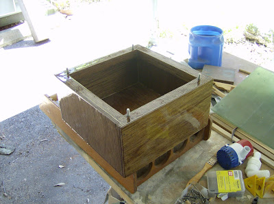
I rough cut the panels to shape using my saber saw. Trimming to the finished edge line was easy. I have a workbench with a piece of aluminum screwed to the edge. I line the cut line up with the aluminum and clamp the plywood in place with a couple of quick release clamps. A router bit with a ball bearing on the end rides on the aluminum edge, trimming the panel to shape quickly and accurately.

I marked the location of the teak trim strips on the face of the panels and cut the center of the panels out, leaving a 2” rim or frame around the edge to allow access to the overhead equipment and fasteners. The cutouts also lightened the panels considerably.

I used a round-over bit in my router to ease the inside edges of the panel openings.  To save some time and overhead work, I painted the panels at this time. I left the rear or upper side of the panels uncoated for the epoxy that would hold the panels in place.

NOTE: I usually give plywood a coat or two of epoxy for protection. I only did one panel this way and found that I couldn’t drive the staples for the Velcro into it!

Panel Installation
The entire overhead was washed down and then wiped with acetone. The areas where the panels were to be bonded in place were lightly sanded with 80-grit sandpaper.

The center panels were installed first and lined up with the centerline established earlier. The cabin top on my boat is cored, which allowed me to fasten the panels in place with stainless steel self-tapping screws.

Once the panels were all in place and adjusted to give a smooth, level surface, I removed them one at a time. As a panel was removed, I gave the back or upper side a coat of epoxy, which soaked into the bare plywood. I then applied a generous amount of epoxy/filler, mixed to peanut-butter consistency, to the epoxy coated plywood and the panel was screwed back in place.

Once all the panels were bonded and screwed in place, I gave the entire overhead a light sanding with 80-grit sandpaper, then primed and painted any bare areas.

Trim Installation
Most of the teak strips were standard 1-3/16” teak battens. I decided to install 1” x 3” mahogany trim strips above the inside handrails. This spaced them out so they were integrated into the overall panel design. Longer fasteners would be used to re-bolt the handrails in place. Since these handrail trim strips were to be bolted in place and were substantial pieces of lumber, I added eyebolt anchors for future lee cloths. The mahogany was stained with Minwax Special Walnut to match the existing teak décor.

Starting from the center, the teak trim was cut to size and screwed in place using #6-3/4” flathead self-tapping screws. You could countersink sink and bung them if you like but I have an aversion to bungs. Once the strips were all in place, I removed them and gave them all six coats of Interlux #60 Rubbed-Effect varnish before reinstalling them.

Removable Panels
I again made patterns for the removable panels from artist’s foam board, recycling the foam patterns from the MDO panels. The patterns were cut to allow a 1/16” gap around all the edges to allow for the thickness of the vinyl material. I cut the panels from 1/4” exterior luan plywood, with the edges sanded to a slightly rounded shape and marked which side faced the vinyl covering.

I covered the panels with a white marine upholstery vinyl I bought at a surplus fabric store. The fabric was placed on a table with the good side down. The panel was placed on top of the vinyl, making sure the proper side is down against the vinyl and cut the vinyl around the panel allowing about 2” around each side. I used an Exacto knife with a #11 blade for all my vinyl cutting and trimming.

Starting from the center of one side, I folded the fabric over and stapled it in place, using 1/4” Monel staples. I then moved to the opposite side and stapled that center in place. Working from the center out, I stapled the vinyl in place, stretching it as tight as I could.

The corners were then trimmed and stapled in place. It would be a good idea to make a couple of small sample panels and practice your stapling and trimming on them before the real thing. Develop your skill with the corners as these take the most time.

Final Assembly
All the removable panels are held in place with adhesive-backed 3/4” wide Velcro.
Velcro has a hook side and a loop side. I decided that all the hook tape would go on MDO panels and the loops on the removable panels. This was just to make sure I kept everything sorted out right. The adhesive couldn’t be depended upon to hold the Velcro in place indefinitely, so I also stapled the Velcro in place with an electric stapler.

With the Velcro firmly attached, I could then press the panels in place. It’s amazing how tightly the Velcro holds the panels in place. I not only haven’t had any panels come loose, I actually have to pry them off. I found the tool that paint stores sell to open paint cans ideal for this job.

Recap
I know this all sounds like a LOT of work, but it actually went surprisingly fast. Would I do it again? You bet!  I love the way it looks and the easy access it provides to the underside of the cabin overhead. It’s a winner as far as I’m concernened.
  DS-Overhead01
DS-Overhead03DS-Overhead02 

  DS-Overhead04
 Making foam board patterns for MDO plywood panels
  DS-Overhead05
MDO panels cut out, painted and ready to install
  DS-Overhead06
Aligning panels with self-tapping screws
  DS-Overhead07
MDO panels epoxied and screwed in place.
  DS-Overhead08
Installing teak trim strips
  DS-Overhead09
Stapling Velcro on vinyl covered removable panels
  DS-Overhead10
Velcro stapled on MDO panel
  DS-Overhead11
Finished panelized overhead

Sunday, December 18, 2011

Setting up an Icom 802 SSB (or other radio types) to prevent RFI

I came across this excellent explanation of  RFI in relationship to boat radio installations. We have an Icom 802 installation with excellent transmit and receive. In Fiji, we could clearly talk to people in Florida and other states. Most stations said we were 5x9. Our difference to the diagrams below is that we have 1. our antenna tuner ground is connected to a bronze plate via copper foil, and no other ground connection is tied to it. This is alluded to in the article below as a possible solution proposed by Henry VE0ME.  2. Our transmitter is not chassis grounded. Just grounded through the -ve supply; for the same reason; also to prevent a ground loop. 3. We noticed a dramatic improvement in our setup when we installed a line isolator. 4. Ferrite chokes also help with various other systems that pick up the RFI. My thanks goes to Jim Corenman for his article and I hope he doesn't mind me reproducing it.

Radio transmitters have a great fondness for causing interference. This is not surprising, since their primary job is to pump 100 watts or more of radio energy into the sky. Ideally all of this energy would be sent off towards the distant receiver, but this is not the case. Antennas, particularly small ones, radiate in all directions, and worse yet, any imbalance in the antenna system causes the coax cable, power wires, and every other interconnection to become part of the antenna system and radiate also. In the days before digital communications this was a nuisance at worse, but when modems and computers get interconnected with transmitters and radios the potential for chaos is great. This is especially problematic for small installations such as boats and RV's where the antenna and ground system literally wrap around the radio and other components.
With respect to HF email, there are two primary symptoms that can be traced to wayward RF energy: distortion of the transmitted audio signal, and data errors between the computer and modem. The distortion problem is subtle because you will rarely hear it yourself. But if your transmitted signal gets back into the audio connection between the modem and transmitter, then it can be rectified and produce its own audio signal, which will be transmitted and produce more interference, etc.. It is very much like the "howl" that emits from a public-address system when the gain is turned up too high, noise feeding upon itself.
Data errors can occur in the modem's serial-port connection. These will usually be detected by the error checking associated with binary modes but it will not be at all obvious that RF is to blame. And if ASCII mode is used then the errors may simply be missed. Errors can happen either sending or receiving messages. If sending, then errors are likely at the beginning of the message transmission, as the computer is busy sending data to the controller's buffer memory at the same time that the controller is sending the beginning of the message over the radio. When receiving a message, the incoming data is usually being transferred to the computer at the same time that the controller is transmitting the "Ack" (Acknowledge) burst back to the sending station. In either case there are serial data transfers happening at the same time that the radio is transmitting digital data.
If an ASCII transmission is in progress then the usual symptom is that characters are lost from the message. Given the general lack of attention paid to spelling these days, such errors usually go unnoticed. If a binary transfer is in progress then a format or checksum error generally occurs because the binary protocol includes error checking. If an error is detected then an error message is sent and a disconnect occurs. Errors of this type are almost always related to RF interference related to ground system problems.
Airmail logs incoming serial-port errors in its Logfile.txt file, located in the c:\program files\airmail\ folder. Open this file and look for something resembling "comm: Error reported to input: 2", this indicates a framing error detected by airmail's serial-input driver. This may also correlate to a disconnect due to a binary format or checksum error. Note that errors in outgoing data would be detected by the controller and not by Airmail, and usually result in lost characters with no other indication of trouble. For the PTC-II controller, Airmail now uses CRC-Host mode which was developed for precisely this reason and which detects and corrects serial-port data errors. (There will be a "retry" entry in Airmail's log file).
Ground systems:
The usual marine antenna/ground system consists of an automatic tuner at the base of the backstay or stern-mounted vertical antenna, a grounding strap from the tuner to a ground system, and a coax cable to the transceiver which itself is usually grounded. Ideally all of the antenna current flows between the antenna wire and the seawater ground system through the tuner, and with a perfect ground system at the tuner then that is what would happen (see Fig. 1).

But grounds are never perfect, and even a ground connected to a large external metal keel has a ground strap of some length which can develop some resistance (impedance) at certain frequencies. If there were no other path then the impedance of the ground system wouldn't matter, but the radio itself is always grounded, either directly or via the DC power wiring, and the nice fat shield on the coax cable provides a good ground conductor. Note that the transmitted signal is balanced between the inner conductor and shield, this can be considered "inside" the coax caable and will not radiate. The stray ground path is on the shield alone, an unbalanced current, and will radiate. This is called a ground loop (see Fig. 2). Other loops are formed by the cables that connect the controller and computer, and their 12V power connections (which themselves are always grounded somewhere).
These ground loops have impedance just like any other wire, and DC wiring in particular makes a pretty poor ground conductor. RF antenna currents using these ground loops as alternative ground paths will radiate interference signals into other cables (just like an antenna) as well as by simple voltage drops due to the impedance of the ground loops themselves. These interference signals will raise havoc with everything.
It would seem attractive to simply beef up the ground system, i.e. reduce its impedance and make that path more attractive. This will certainly help and is a good first step, but it is equally important to make the unwanted paths less attractive.
The solution:
Changing frequencies will typically change the problem, making it better or worse depending on how the impedance of the various ground paths change with frequency. Reducing the output power will always reduce the interference, and is a definitive test to verify that the problem is RF-related (as long as there is enough power to maintain a good link). A permanent solution has three parts:

Make the primary ground system as good as possible;

Make the tuner-to-radio-to-ground path via the coax shield less attractive by using a ferrite "line isolator" add impedance to that loop;

and break up any additional ground loops between radio, controller and computer with clip-on ferrite chokes.
Task 1.
The first task is a careful review of the ground system connected to the tuner. The backstay or vertical antenna is only half of the antenna system, the other half being the ground system. Different frequencies will "see" the ground differently, so what works on one frequency band may not work well on another. Higher frequency signals (21-28 MHz) have a shorter wavelength and need a few square meters (tens of square feet) of metal surface located close to the tuner. Because the square-footage requirement is lower, a direct seawater connection is less important. Lower frequencies (7 to 10 MHz) have a longer wavelength and need more square footage of ground plane than can easily be provided, so a good seawater connection is required. This requires a few square feet of seawater contact but does not need to be as close as it would in order to be effective at high frequencies.
So the ideal ground system is a combination of a ground plane laid against the hull near the tuner, plus a connection to the engine, metal tanks, and any other large metal, and a connection to an external keel or other large underwater metal. These should all be interconnected with a network of 3-4" copper strap which will have a low impedance at all frequencies.
Consider electrolysis when connecting external metal parts (such as a through-hull or prop strut) to the ground system. You will never create a new problem by connecting underwater metal that are already connected to the green-wire DC bonding system, but connecting metal that was previously isolated can create a new electrolysis problem. If in doubt then provide a DC block. Stan Honey's method is simple and effective: cut a quarter-inch gap in the copper foil, and bridge that gap with a dozen ceramic disc capacitors (.01uF line-bypass caps would be a suitable choice). This blocks DC electrolysis currents while providing a low-impedance RF path for antenna currents.
Henry VE0ME, a Canadian ham of some considerable experience, favors an separate antenna ground with no connection to the rest of a vessel's ground system. In other words, run a ground strap from the tuner ground to a large underwater plate (such as the largest-sized Dynaplate), but do not connect this plate to the rest of the ship's ground system. Splitting the ground system this way would break up the major ground loop shown in fig. 2. The key to making this method work is providing a large enough ground plate for the isolated tuner ground, the smaller Dynaplates are not adequate. The disadvantages are those associated with grounding plates in general, drag unless the plate is set flush, and concerns about electrolysis.
For more information on grounding and electrolysis, see Stan Honey's excellent article in Practical Sailor, October 15, 1996 issue.
Task 2.
After we've done what we can with the ground, the second job is to make the alternative ground paths less attractive to the antenna currents. That is done by adding RF impedance to the coax, in the form of a Line Isolator (a large ferrite choke) or multiple clip-on ferrites. This adds impedance to unbalanced common-mode currents such as the ground currents using the shield as an RF path. The transmitter output to the tuner is a balanced signal, i.e. there are equal and opposite currents flowing in the shield and inner conductor). The net current from a balanced signal through the ferrite is zero, so there is no attenuation at all, i.e. zero impedance. But antenna currents using the shield as a ground path flow in one direction only and see the ferrite as an impedance (see Fig 3).
A typical line isolator is about 20 turns of RG-8X around a ferrite rod inside a plastic housing with a female coax connector on each end. Our favorite is the Radio Works model T-4 (ungrounded), about $30 from Radio Works (http://www.radioworks.com/ which also has a good discussion of grounding techniques), or also available for a few extra dollars from Farallon Electronics (gofarallon@aol.com) or HF Radio in Alameda (Don@hfradio.com). You will also need a male-male coax jumper to connect the line isolator to the tuner, as the line isolator comes with two female connectors. Clip-on ferrites will do the same job, but it would take a dozen or more to have the same effectiveness.
The best place to locate a line isolator is close to the tuner itself. In terms of ground currents it doesn't matter where it is located, but if the coax is long then it will still be able to radiate some signal if the line isolator is located at the radio end of the coax.
In addition to the line isolator on the tuner coax, one or more clip-on ferrites should also be added to the tuner control wires. These control signals are usually grounded to the tuner ground, and provide an alternative ground path if not blocked. An alternative to multiple ferrites is to use the large size and loop the wire through it a few times.
Adding a line isolator (and ferrites to the tuner control cable) should stop most of the ground currents from taking the detour through the "radio shack", but will not substitute for an adequate ground system. And of course never add any sort of ferrite choke to the ground connection itself. Many users have also reported that adding a line isolator also cleans up other problems such as autopilot interference, but that will depend on how the other equipment is configured.
Task 3.
Providing a good tuner ground and isolating the alternative coax path are the most important tasks, but while we are cleaning things up we should also break up the ground loops between the radio, controller and computer.
Isolating the ground loops is again done by adding common-mode impedance, in this case in the form of clip-on ferrites (see Fig 3 again). These are small split ferrite cylinders, about 3/4" in diameter, 1-1/4" long, with a 1/4" hole through the middle for a cable. Clip-on ferrites are sold by Radio Shack, but better ones are made by Fair-Rite, their part number for type-43 material in a 1/4" hole size is P/N 04-43-164-251 and available from Newark Electronics (http://www.newark.com/). Fair-Rite's type-31 material performs a little better at HF radio frequencies, their part number is 04-31-164-281 for the 1/4" hole size, and 04-31-164-181 for the 1/2" hole size. The type-31 parts are not sold by Newark but are available with a $50 minimum from Amidon and stocked by many dealers.
Use one ferrite to each end of the computer-to-controller cable, and one at each end of the controller-to-radio cable. And don't forget the tuner cable as noted above. The signals inside the cable will not be effected, only the ground currents trying to use the cable shield as an "sneak" path.
Important: The ferrite halves must meet perfectly in order to be effective. If in doubt, remove the ferrite halves from their plastic housing and secure with tape and/or tie-wraps.
And also make sure that the cables are properly shielded, with the shield connected to the connector shell (and equipment chassis) at both ends. This can be verified with an ohmmeter, and if the metal shells of the DIN or DB-style rectangular connector at each end are connected, then the shield is terminated correctly.
Metal boats:
Steel or aluminum boats don't have a problem with the ground system, but aluminum boats in particular usually have isolated 12V neutral wiring to protect against electrolysis and are subject to significant interference problems. In some cases the problem seems to be much worse than with a fiberglass or wood boat, probably because any stray RF energy is trapped inside a shielded box (the hull), analogous to the proverbial "fox in the henhouse".
The steps outlined above should be equally effective with metal boats. The line isolator in particular should eliminate the stray RF at the source and would be the logical first step. If additional help is needed, the 12V negative connections to the computer, controller and radio can be RF-grounded using capacitors to provide a RF ground with DC blocking. Also provide a similar capacitively-coupled RF ground for the radio chassis. Ceramic-disc capacitors are a good choice for this duty, and a dozen 0.01 line-voltage type capacitors wired in parallel will provide an inexpensive and low-impedance path for HF frequencies.


Saturday, December 17, 2011

Sail Ties

Over at Sail Delmarva, he has come up with a nice and cheap way to make sail ties. Here's how he did it.....

In the West Marine catalog--or any supplier for that matter--they sell prefabricated sail ties for ridiculous prices. My boat came with 2 sets of 2 types. I tried some webbing with Fastex buckles--something I had. They all stink. We used some for other things and cut some up to use the materials for other things. All rubbish.

Having completed my Practical Sailor article on washing rope, I was faced with piles of clean ropes in various states of disrepair. Some was ancient crap, destroyed in the testing. A few bits tie Jessica's kayak to the car or the railing of the boat. Some remains in a basket, waiting some future purpose. Most puzzling was the new dock lines that were herniated and ruined in the washing process. I had 100 feet of new, soft 1/2-inch nylon dockline that simply had a tangled core. I pulled the core out--it slipped out in seconds--and played with both parts,  the core and the cover, while watching a DVD; something to keep the hands busy. Separately, they are so loose and and easy to splice, it became a game to see what could be done. Toys for sailors.

The core was pitched. Other than recyclable fiber, I couldn't dream a purpose. To loose and snag prone.
 The cover is another matter. It's a sort of webbing, or a very hollow single braid rope, super-easy to splice. Just screwing around, sitting on the boat one evening while watching "Cast Away" for the 10th time, I found myself making sail ties from this, a sort of strop. It  felt old school and relaxing... and they are the best ties I have found.

  • The material is soft and easy on the sails. 
  • A brommel splice is fast and  few stitches lock it. 
  • The eye is just large enough to pass a double over hand knot, which is nice and square and never slips out. 
  • The flattened profile of the hollow braid grips the stopper knot better than round rope, without need for an overly tight eye. 
  • The pointed tail makes threading them simple; I can take put them on or take them off in the dark with gloves on, in moments.
  • There is no hard buckle or bozo ball to step on.
  • There is no knot to seize-up after wet dry cycling.
  • They are not adjustable (you can move the knot, of course), but if made to fit there is no need.

Try it. It seems wasteful, just using the cover, but short bits of used rope should do. Normally old rope cannot be spliced, but I think you'll find the cover alone is different. A different spin on strops.

Friday, December 16, 2011

The New Pactor 4 modem

SCS has announced the new Pactor 4 modem which is twice as fast as the pactor 3. Click here for further specification. Here is there intro......
SCS is proud to present its new P4dragon DR-7800, a completely new development, and the first PACTOR-4 capable short-wave modem. P4dragon stands for the most ingenious data transfer algorithms and the highest computing power possible in PACTOR controllers of the 4th generation.

The fast quad-core DSP used in the DR-7800 enables for the very first time, a high data rate, approaching very close to the Shannon limit, as well as an extremely high immunity to interference. PACTOR-4, with its 10 speed levels and adaptive equalizer, adjusts itself ideally to varying channel conditions, and guarantees reliable data transfer even under very poor propagation conditions. Due to this high reliability, P4dragon modems allow transmission of safety relevant data via shortwave, and provide an excellent value for money when compared to many satellite services.

Sacraficial Anode Line Cutter Assembly

I found these anode/linecutters after searching for a line cutter for my Boat. They can be seen in the video with the company hype. I am fitting these for the next cruising season. They cost a little more than the zinc themselves; $34USD for a 1.5 inch shaft. I thought they may be of interest to other boaties.

Tuesday, December 6, 2011

Sump Box for the Bilge

The people over at Carbo Rico_Tiburon36 have built a very nice sump box here's how they did it..........
I needed to add a separate sump to our grey water system. I have a store bought sump from Rule in the forward end of the bilge for the head and shower, but needed one to handle everything else including it. At a $100 bucks or more for one of these plastic boxes, I figured I could make one for a lot less.
Here is how I did it. You can build one too. It's fairly simple. I must add I had some scrap Plexiglas already. I bought the 500 gph bilge pump on ebay. The rest was scrap pieces of marine plywood.

Box measure 11x11x6 inches. It is 1/2 inch ply with 3/4 x 1 inch around the inside for a lip to help seal it and give a place to mount the bolts. The plastic screen inside is actually from a craft store. It is used for some kind of needle work.

Build the box. Then give it several coats of thinned epoxy inside and out. Save money, Don't buy CPES epoxy, just cut your already mixed epoxy with some MEK (NOT MEKP), thin till it's just a little thicker than water, almost half and half mix. MEK is just like Acetone, but evaporates much slower. Let it cure between coats, but put the first 2 coats on while still green. Sand for the last coat and thin it only a little or maybe not at all. You'll know you have enough coats when it is very shiny when finished.

Side note; this little trick will help you fix rotted post and the like without buying special epoxy. I actually apply it to porch post and columns before installing them. Then they never rot.

I used 1/4 inch bolts for the lid. Insert them as you make the box.

From Sump


Fit Plexiglas lid.

From Sump


Install pump and float switch.

From Sump


Install all the fittings in the box and screen plus the fuse holder outside.

From Sump


From Sump


Then install it. I eliminated 12 thru hulls with these two sumps. Now I only have 3 thru hulls.
I mounted it to the bilge with some stainless brackets I had. Screw them to the side of the box, make some pads that can be epoxied to the bilge , with bolts so that the whole thing is removable.
It is under the engine, but hopefully it will be somewhat accessible.


Heat Exchanger Modification

After installing a new heat exchanger for our Gen Set, we had no further issues. However, the primary issue of "stuff growing inside our heat exchanger" has not been resolved, and, because the Fischer Panda generator has it's heat exchanger in such an awkward place to service, we decided to modify our new heat exchanger so that it can be cleaned out with the minimal of fuss annually.
  We took our heat exchanger and removed the ends by "unsoldering", so that new ends could be attached that would allow for easy removal.
We attached some brass ends (by soldering) with a reducing thread and then used a threaded cap, and finally a threaded tail to give us our 19mm hose fitting.


In the picture to the right, you can see how easily it is now to remove the end caps to clean the internals of the heat exchanger. And with it's new mounted location, we should no longer have issues with our Gen Set shutting down to over heating.
Since we have been dealing with heat exchangers, we have learnt something. Heat exchangers made from copper and nickel last a lot longer than those just made from copper. All heat exchangers should have some provision for cleaning the "internals". A sacrificial anode is a must. A fresh water flush through the engine and heat exchanger before turning the engine off for prolonged periods, increases the life of the engine and heat exchanger.