Pages

Friday, November 14, 2014

Quick and Effective, Water Hose Repair


I've been cruising for a while now, and sometimes you can not get proper boat bits in the more remote parts of the world.
Recently I replaced a raw water hose which had a steel spiral wound "spring" in the core of the water hose, which gave the hose "anti kinking properties" when bent around corners.
This hose however corroded at the ends and the hose started to leak at the ends.
I replaced it with this hose shown to the left. Good quality radiator hose without the wire. When I installed the hose, it took the radius I imposed on it just fine. However after some months of running the engine, I discovered the hose kinked like that shown to the left.


I had no new hose other than the same type to install and lamented having not purchased the spiral wire bound hose to replace the original. I also didn't have a 25mm elbow to replace the kink with, BUT did have 38mm radiator hose pieces. I used one of these pieces to make the bend. The kinked hose was cut at the kink and the ends push fitted into the elbow.


Finally I used the tool shown to the left (which an explanation of how to use can be found here).
The hose has been installed for a month now, and is both water tight and kink free. This will do until I can purchase the original type of hose which I will carry spare lenghs for future replacement

Saturday, July 5, 2014

Portable Fuel Transfer Pump and Filter

Pump and Filter in Plastic Box
Have you ever siphoned fuel and got a mouth full of diesel?
Have you  ever transferred fuel to your boat with jerry cans and other fuel containers with no pouring spouts?
Need a quick and easy method to transfer fuel?
I recently made a fuel transfer pump with filter for transferring diesel fuel from tank to tank or jerry can. I needed this through out South East Asia, where the fuel most often was not clean. I also had to obtain fuel in jerry cans as fuel docks were few and far between. This necessitated pumping out of the jerry cans so that what went into my tanks, went through a filter first. Since then, I have also used it to pump fuel between tanks so that I can clean the fuel tanks from time to time. In fact, if my tank is not heavily contaminated, I use the pump system shown here to "vacuum" the bottom of the tank. The fuel filter stops all the contaminants and separates the water out.

 CAV Filter
I used a CAV filter housing similar to the one shown to the right, along with an oil tranfer pump (12V). The filters for these are readily available in most countries around the world, and quite cheap.
The oil transfer pump, which I use for the diesel fuel, has a switch on the end of the pump, which makes for easy on/off operation.
It was just a case of connecting the hoses, hose tails, and wiring with a long piece of duplex wire with alligator clips to connect to a power source. This was all placed in a plastic box for ease of handling, and to keep it "water proof" as I store it in my aft lockers, where sometimes sea water will get in.
Packed and ready for it's Lid
The filter housing was mounted to the side of the box to keep it upright.
Hoses are easily stored with the pump and the whole setup is ready to go. I used fuel line hose.
Warning! The pump I used is OK for diesel fuel, but Not  for use with petrol.
To keep the whole lot from having fuel leak into the box, I used rubber bungs on the end of the hose. You can see one on the hose in the picture to the left.
You can also use the box for a diesel rag, if you use one from time to time
The type of pump used in my fuel transfer/filter box
.


Thursday, July 3, 2014

Adapting Old Water Pipe to New


On my boat, I have half inch water pipe made from a "plastic" and flexible material. Unfortunately, this is now outdated, with most boats now using 15mm flexible pipe. This presents problems with adapting the old to the new. Also, the fittings used to connect this pipe, (black elbow to left) are no longer available and sometimes come apart.
In New Zealand they have a 12.5mm pipe with push in fittings. You would think the half inch pipe might fit...., but no, it doesn't.
So here's how I have over come this problem...
Fortunately this plastic pipe is similar in size to copper half inch pipe and the compression fittings are available at most plumbing hardware stores.


To the right is a photo of old and new fittings used to attach to the faucet at the sink.


To the left is the new compression fitting disassembled. To the inside, is a rubber ring and star washer to grip the pipe.


Compare the above photo to the plastic one to the right. They work in a very similar fashion.


The fittings come in a number of arrangements. I bought a straight connector, a "T", and end threaded adapter.


To the right, the nut goes on first, then the star washer, followed by the rubber washer. Once the pipe is inserted into the fitting, the nut is screwed down to secure the pipe.


Now, the fitting, made for copper pipe, doesn't quite fit the plastic pipe, so a little modification has to be done.
First, use a dremel stone to slightly enlarge the hole in the center of the compression nut so that it slides over the plastic pipe. It only needs a "human hair" thickness taken off.


The pipe also has to fit the fitting. This requires a little sanding on the end so the pipe fits, snugly.
You can see that, in the photo to the right.


When assembling, slide the fitting onto the end of the pipe and mark with a felt pen. Slide off the fitting and then with the nut first, slide on the star washer with the points towards the yet to be fitted copper fitting. Slide this on till just past the pen line so that when the rubber washer is placed, it is is pushed on till just past the pen line.


To the right is the fitting about to have the nut screwed on to make the compression. Once that is done, regular plumbing fittings can be attached.


I've also had success with another type of compression fitting using a copper compression sleeve shown to the left. However, on occasion, some of these have leaked due to the copper sleeve not being perfectly aligned before compression. One has to remove a short piece of the pipe, (because the compressed sleeve is almost impossible to get off) and place a new compression sleeve on and make sure it is seated correctly before tightening up. It seems to me, the compression fitting with the rubber washer is a better fit and can be reused if one has to undo the nut.

Another method, show to the right is to get a hose tail with a plumbing threaded end, and attach with a suitable hose clip , or for a more secure fitting, use the wire tightener, and it's use can be viewed here.

Friday, May 16, 2014

Hole Saw Enlarger

Here's a handy tool. A Hole Saw Enlarger.

Expands holes in tight retrofit situations. Applications are many and varied but are not limited to, door lock installations, through holes, and for conduit fittings.


FEATURES

  • Changes hole saw sizes in seconds - Enlarging a hole is quick and easy with the HE1 Hole Enlarger Kit from Bosch. You use two hole saws, the original saw that you cut the first hole with and the hole saw size you want the new hole to be. You combine both hole saws with the dual adapter and us the mandrel to attach it to your drill. Insert the first hole saw tip into the hole and start enlarging
  • Provides easy plug removal with angled reinsertion of the pilot bit
  • Makes the Bosch Quick Change system universal. Quick change adapters fit most major brand of holesaws
  • Enlarges any existing hole that matches a hole saw diameter, starting with 9/16-in - 6-in

Monday, April 28, 2014

NMEA 2000; Some Limitations and Cautions

The intent of this article is to familiarize the boat owner with some limitations that I and others have found with NMEA2000.

NMEA2000 technology was borrowed from the non-marine industry (CAN bus) and adapted to the boating industry. Unfortunately, that has left it with some short comings which I will attempt to explain in this article. Also along the way, some manufacturer's have seen fit to produce products that don't fully comply with the nmea standard.

So what is NMEA2000?
The idea for which the bus was developed, is effectively to use a display from manufacturer A, and possibly a sensor from manufacturer B, connect them both to the NMEA2000 network, and the display will show what the sensor detects. In the ideal network, this should be possible. Even NMEA 0183 could do this in a limited way.

Prior to the development of NMEA2000, the boating industry used an older standard for interconnecting equipment; NMEA 0183. This standard was meant to provide a point-to-point connection between two devices. Obviously the point-to-point scheme between just two devices, is very limited. NMEA 0183 is great for simple applications. It’s so good, in fact, that an updated, high-speed version has been introduced to handle the information from AIS receivers. But a truly integrated system requires more than NMEA 0183 can provide.  NMEA 2000 is 50 times faster than its predecessor, NMEA 0183, so it can handle data from up to 50 different devices, but it’s still not the complete answer. That’s because those message headers can occupy any amount of data up to half of each frame. The result is that NMEA 2000 is too slow and inefficient to be useful for complex data such as video images or cartography.  NMEA2000 is a shared network, not unlike Ethernet, where many sensors, displays, and control units can be interconnected on one common network but has severe bandwidth restrictions to what is available over ethernet. 

Also, when in implementing the standard, manufacturers, for whatever reason, have tended to "go their own way" with NMEA2000. For instance, some of the first generation NMEA2000 hardware used different (and incompatible) connectors, depending on the manufacturer. An example of the first generation incompatible connectors are the Lowrance "Blue" connectors, which will only connect to a Lowrance NMEA2000 device. Fortunately, most manufacturers have seen fit to finally embrace the standard, and Lowrance's "Red" connectors are NMEA2000 standardized, and will interconnect with any other vendor's NMEA2000 connector. 

In addition, Maretron does provide field installable connectors that you can use to correct the early manufactured non-standard connections. For instance, with Lowrance "Blue" devices, I cut the connector off and installed a Maretron field installable connector to make them compatible with the network.

However, there are still some incompatibilities across the various manufacturers as each manufacturer is allowed to develop their own private data packets in addition to the standard (or public) packets defined by the NMEA2000 standard and used by everybody. As well, not every device understands every packet - even the standard NMEA2000 defined packets. That rudder packet may be ignored by a certain display if it doesn't have the capability to display rudder information. For that reason, you cannot simply use any display with any sensor. You may need to review the capabilities of the display unit you wish to use to ensure it can read the sensor. Fortunately, most manufacturers do publish this information.

So this leads me to my first caution...
Because of these "private data packets",  some vendors may purposely use private PGNs (those that only that manufacturer's equipment understands). So a certain device may only be able to be read  that manufacturer's equipment, regardless of whether or not the device has a standard connector.
Also, many sensors must be programmed before use, and this usually requires a display unit of the same manufacturer to program them. However, once programmed - the sensor may be able to be detected by any other manufacturer's product. This incompatibility still exists to some degree, so be aware when mixing products from different manufacturers that you may run across a few problems.

Building a Network
NMEA-2000 initially provided for two network cabling schemes; called Mini and Micro. Maretron now offers a third scheme called Mid. So the first question to answer is which one do I use? While each cabling scheme is identical in their bus configuration, the major difference is the capacity each network will provide. They are:

Since each device on the network requires a different amount of power (i.e. a display unit is likely to demand more power than a sensor), some thought must be given to how much total power the various devices require. NMEA-2000 includes a LEN specification that every NMEA-2000 device must provide. ( 1 LEN = 50mA ) Therefore, if a sensor states that it has a LEN of 5, you know that it's current requirement is 250mA. The idea of the LEN is to add them all up, and they should be less than the maximum LEN of the cable. From the chart, essentially the decision of which cable to use is determined by the length of the network you want to install, and the number of devices you need to support, and their total current requirement.

But there are limitations to the network.
The cable distance between any two points (a point being an electronic product or terminator) must not exceed 250 meters (820 feet) for a system based on the Mini or Mid trunk cable or 100 meters (328 feet) for a system based on a Micro trunk cable
AND the cumulative drop line length is the sum of all drop lines, Mini, Mid or Micro cable in the cabling system; This sum cannot exceed 78 meters (256 feet) and no single device can be more than 6 meters (20 feet) from the trunk line.
This places limits for sail boats with masts greater than 20 feet. Effectively it means the main trunk of the Network has to go up the mast, and  to cover instruments or sensors forward of the mast the main trunk has to do a big "U" back, or use a drop line no more than 20 feet. If one wants to put more than one sensor at the top of the mast, the wiring becomes more of a problem with probably the "T' junctions and terminator living outside the mast in the elements.

BUT in addition to this, excessive voltage drop can be an issue when using Micro cable, due to the small size of the power wires within the backbone. Especially on long cable runs you can have excessive voltage drop, even if the total power required by all of the devices is less than the LEN rating of the cable. To determine the voltage drop, an easy formula can be used: Voltage drop = LEN X Cable Length(in meters) X Cable Resistance(in ohms)/100

Clearly for sailboats the micro cable probably can't be used, but one could use a Micro network with a Mid backbone cable. Essentially the only difference is that the Mid cable uses 16 AWG power wires, where the Micro cable uses 22 AWG. Otherwise, all of the connectors and terminators are identical. This is the most cost-effective solution as Mid cables do not really cost much more than a Micro cable, and you can still use the less expensive Micro connectors and drop cables.

One important item that needs repeating is voltage drop.  Attention must also be given to the feed wires. The wiring route from the battery to the NMEA22000 power tee should be minimized to reduce voltage loss. This is sometimes difficult as often, the power switch for the network logically belongs at the helm, however (especially with a center-feed network), the power tee may be located some distance from the helm. One solution is to install a relay near the power tap, which is switched at the helm. The relay would allow a remote switch at the helm to turn the network on or off with minimum voltage loss.

Now my second caution......
Now consider this. If there is a problem with the NMEA2000 back bone, every piece of gear on that network that is dependent on it, stops working. Everything, that comunicates with each other, becomes non effective.
  • The GPS stops working, including the plotter
  • The fluxgate compass  doesn't work
  • Engine instruments don't work
  • AIS doesn't show anything
  • the autpilot stops working because it doesn't get a heading from the compass 
Get the picture? Now we all know this will happen at the most inopportune  moment.  One may start (trying to find the fault) by unconnecting and reconnecting every connector on the back bone to make sure that they are properly connected. There can be meters of cabling in hard to reach and dar,k places on your boat and all it takes is just one of those connectors to fail and it's "lights out". And if the problem is intermittent, as it very likely will be, then the trouble shooting is going to be ten times more difficult. Then if cleaning and reseating connectors or terminators cannot solve a problem, then by all means seek the professional help of an NMEA-certified electronics technician. Good luck with that, in some of the locations we go to!

What we need to think about is what a network failure will do to us on a dark night in a tricky situation. We must have a backup plan. And because of the issues with trouble shooting these complex systems in remote places, it would be good to have a plan for continuing our cruise without all this interconnection potential problems. Here's some things that could help
  •  Have a plotter with a separately connected GPS sensor, or GPS with paper charts, available. Or consider an iPad with it's own charting system. We use it all the time now, to compare two separate chart systems. It has it's own GPS
  • There is a separate AIS unit with its own screen and direct connection to its own GPS within sight of the helm. Some of the latest up market VHF have AIA receivers on the screen.
  • There are backup hard wired, or mechanically connected, engine instruments.
  • And don't forget a properly swung magnetic compass. 
 Now it's not that I'm against NMEA2000. I like the idea of just one cable running the length of the boat. But consider this; since the 14 years NMEA2000 has been out, we now find a class of products specifically marketed to users of existing navigation software that offer to gateway from NMEA2000 physical networks to USB, translating NMEA2000 packets on the fly to NMEA0183 sentences that existing software can read. This reveals that NMEA2000 adds little information and little value to the contents of an NMEA0183 stream of navigation data. The coupling of NMEA2000 to a proprietary physical network is so tight that there is no standard for shipping it over USB, RS232, Ethernet, or any of the other physical networks commonly used in the general computing market at the present time. However, in the near future,  NMEA is going to release a standard called "OneNet" for interfacing NMEA2000 to ethernet and I suspect the bridges to USB etc will appear around the same time.

So when that comes about, are boats then going to run another cabling system around their boat to accommodate for the higher bandwidth of devices today, that NMEA2000 can't handle? It sort of defeats the purpose of running just one cable. NMEA2000 specification itself is proprietary and expensive. Ethernet is more of an open standard and open source and open protocols grow markets and create opportunities. NMEA2000 sharply illustrates the obverse of this point. It is tied tightly to a specific physical networking scheme, and has made the specification expensive and proprietary. And so in 2014, I look at NMEA2000 and see how atypical and archaic it looks. Binary packets instead of HTTP?  Proprietary physical layers that don't lead to a nice plug and play? And bandwidth handicapped! This is not the direction the rest of the Web-enabled  world is moving. Imagine having google earth directly overlayed on to your charts, integrated web tracking of your AIS information as standard on your chartplotter; just to mention of few.

NMEA 2000 operates at 250 kbits/second, very slow compared to Ethernet. Because of this bandwidth limitation, sonar and radar overlays can't be sent over the NMEA 2000 networks, that is why all the major manufacturers have their own proprietary networks for sonar and radar integration with their large display devices. But, NMEA2000 has a few advantages over Ethernet, cost, a collision-less system, time sensitive point to point delivery to name a few. It was developed to function in electrically noisy environments and to have a predictable delivery time for messages. Ethernet does not always provide a real time predictable delivery time or quality of service capabilities.

goal for OneNet is to "Transport NMEA 2000 network messages on Ethernet in a standardized manner" or as the release's subtitle says "Think of it as NMEA 2000 on steroids." That's because OneNet will break out of N2K's speed and node limitations big time, like increasing the maximum number of devices from 50 to over 65,000! (Now, that would be quite a vessel.) - See more at: http://www.panbo.com/archives/2012/08/onenet_nmea_finally_creates_a_marine_ethernet_standard.html#sthash.chOhWjdS.dpuf
Now, I'm not going to comment much about OneNET (as it still hasn't been released in it's final form), but it's stated goal is to transport NMEA2000 packet data on Ethernet in a standardized form. Think of it as NMEA2000 on steroids. This will break out nmea2000 speed limit and node limitations by a huge amount. The number of devices would increase from 50 to over 65,000! I don't see OneNET replaceing NMEA2000 or NMEA 0183 in the near future, but I am left wondering why NMEA has made this protocol so late, with an internet PC centric world everywhere. Also, I suspect, at least initially, it won't play nice with with existing ethernet devices, and I'm pretty sure it won't carry both NMEA2000 packets as well as NMEA0183 data sentences at the same time. You will need to use another gateway for that. However, once they convert NMEA to Ethernet the possibly of connecting to the outside world is endless.

What all this boils down to is that we boaters have three main ways of creating a network, each of which complements the strengths and weaknesses of the others: NMEA 0183 is perfect for very simple systems—it’s tried, tested, and virtually universal. NMEA 2000 is for most current multisensor/multidisplay systems, and Ethernet is suited to handle large volumes of complex data. Your best to consult your marine electronics expert to see what best suits your application. For me, I'm still running mostly NMEA0183, and with that, I have a number of back up solutions which give me confidence that when the lights go out on my main network, I can use the backup to get home safely. By that time, OneNet may be well established, and it could be a good time to upgrade. I'll just have to do my homework on the best system at the time, which is what we all do mostly.


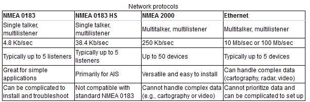
A Comparison of the main types of networks/standards


OneNet will not replace NMEA 2000 or NMEA 0183 within the foreseeable future. Each will have its place on a boat - See more at: http://www.panbo.com/archives/2012/08/onenet_nmea_finally_creates_a_marine_ethernet_standard.html#sthash.chOhWjdS.dpuf
goal for OneNet is to "Transport NMEA 2000 network messages on Ethernet in a standardized manner" or as the release's subtitle says "Think of it as NMEA 2000 on steroids." That's because OneNet will break out of N2K's speed and node limitations big time, like increasing the maximum number of devices from 50 to over 65,000! (Now, that would be quite a vessel.) - See more at: http://www.panbo.com/archives/2012/08/onenet_nmea_finally_creates_a_marine_ethernet_standard.html#sthash.chOhWjdS.dpuf


Sunday, March 30, 2014

Raw Water Pump Mounting Modification

Copper spacer in place ready for mounting
A while ago I replaced my raw water pump for my Westerbeke engine and discovered that the replacement pump had a flat foot for mounting that would not fit in the machined groove of it's mounting bracket. ( machined groove can be seen in last photo). The original pump had been machined to allow for this, but the replacement had not.


Temporary solution


What to do? A quick solution was to place two large flat washers on which would allow the pump to sit flat and square, as well as, being able to slide in and out as I adjust the belt for tension.
The washers were the ideal size, but a better solution was available with a little cooper stock.


Pump mounted
I could of had the pump sent out for machining so that the foot would fit the recessed groove, but instead I had a large flat copper bar made to the dimensions to fit the groove and two holes placed for the holding bolts. This can be seen in place on the photo to the left and placed over the bolts ready for mounting in the top photo.
This means now, that any Sherwood pump I buy to replace, now no longer needs machining to fit the mounting bracket.

Sunday, February 2, 2014

Fischer Panda Generator Bearing Replacement

With this post, I want to advise readers that to do as I have done will probably void your warranty. However, if you are out of warranty, then this is a possible solution. Normally to replace the end bearing would require the complete removal of the engine from the case. Here's how I did it.

Completed job with signs of old bearing overheat.
I discovered that my generator end bearing was making a noise and looking at the end plate, discovered some over heating signs. Time to replace the bearing!

You can see here to the left, the photo shows overheating at the center of the alternator end plate. The brown color is burnt grease which has escaped the bearing. Actually the photo is the completed job before the sound case was put back . However, the "burnt" sign were still visible.

The first thing I did was remove the centre bearing support, on the alternator end plate.


Dry bearing
This required three screws to be removed and longer screws with the same thread placed into three threaded holes on the end plate. By tightening these longer bolts, they pushed the center plate out. You can see three threaded holes in the picture to the right, and three scuff marks where the three extraction bolts pushed up against the end plate to help drive out the center piece.

I modified a puller to fit in the space available, to try to extract the bearing. In the end, so much force was applied, that a foot on one of the legs of the puller broke off.   Soooo, time to remove the end plate and put a heavy bearing puller on it. You can see the sealed bearing has lost it's ability to hold it's own grease.


Trying to remove bearing without taking end plate off.


Engine mount cut in half to facilitate removal. Assembly under way
However, in removing the end plate, I discovered that the engine mount had to be removed, so that access to the bottom last four nuts, could be accessed. However. the engine mount couldn't be removed unless the engine is raised out of it's casing. Something, because of it's weight, would require me to make a gantry to lift the generator. I elected instead, to modify the end of the casing, (seen in photo to right) which allowed me to cut the engine mount in half, which then allowed me to extract the engine mount in two pieces, which then allowed me to remove the final four nuts to remove the end plate.A crow bar(s) was used to support the generator casing while the work was undertaken.

The end plate was removed, and I tried another very heavy duty bearing puller, to no avail.
Protection for windings etc against fine metal dust


Now I was faced with cutting off the bearing with a Dremel. The end plate has a step on the inside surface which fits snugly into the generator casing. The end plate required several screw drivers, wedged in from the side, to get it started; and then I used a crow bar once a gap had been made, to pry it off. Be carefull not to damage either the end plate or generator casing. Use all your levers near the studs that remain on the generator casing, because that is the strongest area.

Bearing installed and generator case end cleaned and repaired


Cut bearing.
There are many methods by which you can get  a "stuck" bearing off it's shaft, but the most popular method seems to be with a Dremel with a cutting wheel, to cut the bearing off the shaft. Usually you cut through the bearing "almost" through it's thickness, and drive with a hammer , a cold chisel into the cut, to help fracture the bearing, and then it is usually easily removed with a couple of screwdrivers. It helps if you make two cuts with the dremel. The first cut weakens the bearing inner race and the second (at 180 degrees to the first) allowes you to 'fracture' the inner race on the shaft.

The outer shell of the bearing and the ball race were very easy to cut off. The inner race was placed next to a shoulder on the shaft, so I couldn't get the dremel saw all the way across. So, I turned it 90 degrees and cut down as far as I dared; starting near the shoulder and working back. It was  tedious, but did a slightly better job than using a grinding stone.

One jacket end cleaned; nine to go.
 After the old bearing was removed, the surface was cleaned up with a sanding wheel using the dremel again. The new bearing was driven onto to the shaft using a drift punch against the inner shell, ensuring it went on square, and knocking alternatively, from side to side.

Now it was time to clean up the surface of both the end plate and alternator casing, for the new casket. However, I found Fischer Panda had epoxied the ends of the water jacket in the casing; placing first a thick gasket like cut out, inside the water jacket, and then the epoxy to the end of the water jacket.

I found one water jacket with nothing in it, but the remains of the epoxy. I proceeded to clean all the water jacket ends and release the epoxy "bungs".

Previous to this job, I had removed my sacrificial anode and found two of the gasket cutouts blocking the water hoses that are involved with the cooling. I wondered where they had come from, and Fischer Panda advised they were from the end plate gasket. Rubbish, The gasket was complete! Now I know. I've also found in the past, some of this epoxy in my heat exchanger. No wonder I've had over heating problems in the past.

Now in cleaning up this epoxy, I found a number of the cut outs had migrated into the water jacket. Lucky I have a special took for grabbing stuff in tight places.


To the left, some of the cutouts and epoxy removed. The smaller bits were not saved


Building up water jacket with J-B Weld
 After cleaning out all the water jackets, I had to build up some areas. The areas of concern were soft aluminum and I used a dremel burr to clean away the soft stuff. Pretty much like a dentist might clean out tooth decay. Because I was not in a position to now order a whole new generator casing, I decided to do a patch job and hope this will last another year, until I can either get the new parts, or a new generator altogether. All the corrosion was at the end of the generator casing, and I suspect the epoxy had some part to play in this. My theory is that when the generator casing was raw water cooled, that the epoxy "traped" sea water and prevented an exchange of clean water, when I did a fresh water flush at the end of each generator run.

I used J-B Weld to build up the "decayed areas", after ensuring the surface for the epoxy was clean and free of dust and "soft" aluminum.
 J-B Weld takes about 4 hours to set and 24 to really harden. Selley's also has a similar product, but it sets in 3-5 minutes according to the directions. However, after trying it on another item, I found I only had about 1 minute of working time. I preferred the longer working time, although I often waited 20 minutes before applying J-B Weld to the surface.

The end of the casing, after the J-B Weld had hardened over night, was leveled with a dremel and fine burr, and checked with a straight edge.

Finally, after all surfaces were cleaned and checked for "Flatness", I used the supplied gasket and applied a thin layer of RTV high temperature gasket cement to both sides of the gasket. All studs were also given a coat of "antiseize" before the plate and nuts were applied. A gentle tap around the outer surface was required because of the shoulder that recesses into the casing. This can be seen in the inside of the gasket to the right.
The nuts were finger tighened, and the RTV allowed an hour to set up. Then final tightening done after the RTV cement had set up.
Engine mounts were applied and the capcitors and air intake module replaced. These were removed to facilitate the job and obtain exposure.
The small piece of generator casing cut out so that I could cut the engine mount in half was placed back with a small piece of aluminum plate, pop riveted to the fibreglass cutout, and screwed to the remaining sound proof case.
The engine and generator case were then filled with fresh water and antifreeze and bleed of all air. This took some time before the correct flow of water was to be had.

I feel that if I had of changed my generator casing to fresh water cooling sooner, that maybe this "corrosion" might not have happened. Regardless, while it was sea water cooled, the anode never deteriorated from it's new condition and feel FP's anode let me down. You can read about how I changed the water cooling here, so that both the generator casing and the engine, enjoyed fresh water only and heat exchanged through a heat exchanger.

Now it's a question of will this repair last a year until I can do a complete alternator casing changeout, and also, do we repair or install new? We have done four hours on the generator, and so far no problems.

Friday, January 3, 2014

CentaCorp Damper Plate Replacement on Westerbeke Engine and Hurth Transmission, along with PYI Flexible Coupler Installation

Damper Plates, which are bolted on the flywheel, provide the damping of drive train forces exerted on the transmission by the engine and propeller.
To the left, is a picture of a typical damper plate. It looks like a clutch plate on a vehicle, but does not have the clutch effect, but is instead bolted to the flywheel. The springs that make up this damper plate provide the damping effect; but over time these springs can loosen and even break.
This brings me to where I needed to replace my damper plate.

What led me to replace the damper plate?
Drive train rattle or transmission rattle on a boat can first be noticed with engine RPM between 550rpm (idle) and around 1000rpm. It starts with a very light rattle but over some miles gradually gets worse to where you suspect something is noisy in the transmission. It can be caused by a number of factors of which is a list here;
  • bent prop shaft
  • out of balance prop
  • worn cutless bearings
  • miss alignment of transmission to shaft
  • loose coupling bolts
  • worn transmission bearings
  • loose or broken engine mounts
and so it goes on, BUT the most common cause is a worn damper plate. Often, with the spring type, the springs shorten with repeated compression and then rattle inside their mounted positions. Some even break.
With my diagnosis of a worn damper plate, I set about getting the parts and equipment together to replace mine. I have a Westerbeke 82B four engine mated to a Hurth Z25 transmission. In the end, I had to go out and buy some new special tools to get the job done. This was done at Rebak Island near Langkawi Island. Not much was available in the haulout yard. Best to do this where the services are close by.

To the right, you can see my transmission with a small heat exchanger on top. The first water hose has been disconnected from it.


Your transmission will require a different method of removal, but here's how I did mine. I removed the boat from the water. I removed the bell housing with the transmission. The damper plate would not come through the bell housing if left in place. Yours may differ.

  • Disconnect all water hoses from heat exchangers and remove heat exchangers
  • undo and remove transmission selector casing from end of transmission housing. This facilitates accessing the drive shaft bolts which sit under the transmission and gave me more space
  • undo transmission/drive shaft coupling bolts
  • undo the grub screws which hold the dripless seal to the shaft.
  • move the shaft back as far as possible. I was able to get 5-6 inches of space
  • remove bell hosing bolts
  • Take the weight of the rear of the engine with a six to one pulley. I used my main sheet block set.
  • remove the rear engine mounts which are attached at the transmission
  • support the transmission with a five to one pulley. I used my vang block set.
  • remove the transmission rearward to disengage, and then up and out
 And to my surprise here's what I found. I removed the six bolts holding the damper plate to the flywheel and inspected the damper plate.
Not a spring type damper plate, but something like the one I'm about to replace with. A damper plate by Centa Corp. You can link to it here. My new damper plate was a Centaflex-DS. Centa has many types of couplers and if you choose to use one of their couplers, they will provide the correct one, once you supply details of engine and transmission.
However the damper plate did indeed need replaceing. The center rubbers were worn so where I could turn the center hub by hand; and the outer rubbers for the second stage were completely gone on one side. I don't know why this has happened, but the engine has done over 3,000 hrs.

The new damper plate showing the other side, is shown to the left.


The transmission with Bell Housing just fits through an engine room doorway; now access can be gained to the damper plate at the flywheel.


The new damper plate was placed on the fly wheel and the bolts torqued. The rest was just a case of reversing the order of disassembly.
While I had this project in hand, I decided to put in one of PYI's flexible shaft couplers.  It is important to get the right coupler, and PYI will calculate which one you need after you give them details of your engine horsepower and transmission details.

This required the shaft being moved back by about 45mm, but I thought this would not harm my current arrangement with the prop some distance from my skeg. Anyway, here is a picture of the shaft coupler in place.

You can see here, that there is not much room from the coupler to the dripless seal. This coupler was a compromise because of the space available. I would have preferred the one recommended by Centa, but with  the dripless seal, there was not enough space.


 Finally, after placeing the boat in the water, we did about 2 hours of motoring. Oh, the quiet! Wonderful!
I had to "burp" the dripless seal to remove the air, but everything went smooth. Even the engine seems to idle smoother, and I don't know if I'm imagining things, but I think I've even picked up a little more speed.
Time; 3 days to remove the transmission. There were some very tight and awkward bolts to get undone. 2.5 days to replace. Not a job for your average boat handyman. Think about getting help if you want to attempt this.